
In an 800 V DC cabinet, a 30 kW power supply with 1 mF input capacitance draws 320 J of energy at plug-in. Using a single MOSFET for linear current limiting, all that energy lands on the device—32 times the 10 ms withstand of a TO-247 package. The dividing line for hot-swap designs is not current, but stored energy.
One-line answer: 800 V and 1 mF yield 320 J. A single-stage linear limiter puts all that energy on one device. First use a resistor to charge the bus to 90%, then let the MOSFET handle the remaining 10%.
320 J decides the approach, not 8 A
The destructive force of inrush is set by capacitor energy, not peak current. On an 800 V bus with 1 mF, stored energy is ½CV² = 320 J. The same 1 mF on a 48 V bus holds only 1.15 J—a 278× difference.
This explains why 48 V experience fails at 800 V. In a 48 V cabinet, an NTC thermistor absorbs inrush energy on the order of 10 J, and its thermal mass handles it. At 800 V, the same NTC must absorb 320 J, causing a 200 K case temperature rise within 300 ms.
Peak current is secondary. With a 100 Ω limiting resistor, peak current is only 8 A—any 10 A device can handle that. What it cannot handle is the energy dissipated during limiting.
Hot-swap surge is the charge and energy drawn from the bus as input capacitance charges from zero to bus voltage when a device is plugged in live. The energy limit equals ½CV², independent of the limiting method.
Limiting method only changes where energy lands
A resistor transfers energy to the resistor; linear limiting transfers it to the pass device. The total is still 320 J. The difference is thermal mass: a resistor can be hundreds of grams of metal, while a MOSFET die is a few milligrams.
Resistor selection depends on pulse withstand, not power rating. A 50 W wirewound resistor can absorb 133 J per pulse; a cement resistor only 40 J; a chip resistor as low as 3 J. For 320 J, only wirewound or aluminum-housed types work.
Charging time with a resistor is set by the time constant. 100 Ω and 1 mF give τ = 100 ms; reaching 95% takes three time constants, or 300 ms. Average dissipation during this time is 1.07 kW, with a peak of 6.4 kW at switch-on.
Linear limiting clamps current at 5 A, so charging time is C×V/I = 160 ms. The pass device dissipation falls linearly from 4 kW to zero, integrating to exactly 320 J.
Based on published parameters: with a single-stage 5 A constant current, the pass device sees 5×400×0.16 = 320 J. A TO-247 package has a 10 ms pulse withstand of about 1 kW, or 10 J—a 32× shortfall. If the bus is first charged to 720 V, the pass device only needs to cover 80 V, reducing energy to 3.2 J—within the safe zone.
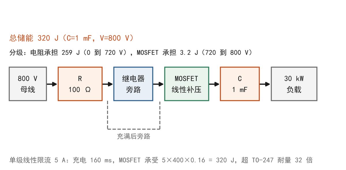
Figure 1: Staged precharge circuit for 800 V input (self-drawn schematic, not a copy of the original).
When one unit draws 320 J from the bus, a 20 mF cabinet bus drops by 20 V, or 2.5%. The other seven supplies have input undervoltage protection set at 700 V, so they do not trip, but each current loop corrects once, superimposing a 200 ms low-frequency envelope on the bus ripple. Servo loads may report a transient warning.
The problem with NTCs is steady state. Cold resistance is 25 Ω, hot resistance drops to 1 Ω. At full load 37.5 A, the drop is 37.5 V and loss is 1.4 kW—like adding a heater to the cabinet. To bypass it, the NTC only limits inrush, same as a fixed resistor.
Staging leaves margin at each step
Staging splits the 320 J into two parts. The resistor handles 259 J from 0 to 720 V; the pass device handles 61 J from 720 to 800 V, but because the voltage difference is only 80 V and time is 16 ms, actual dissipation is 3.2 J.
259 J is still heavy for the resistor. Three 50 W wirewound resistors in parallel, each with 133 J pulse withstand, give 400 J total—80% margin. Temperature rise per switch-on is 90 K, allowing consecutive plug-ins every 60 s.
| Precharge method (800 V, 1 mF, 30 kW) | Peak current | Time to 95% | Energy on limiting device | Size & cost | Verdict (device margin ≥20%) |
| 100 Ω resistor + relay bypass | 8 A | 300 ms | 320 J (resistor) | 3×50 W, $4 | Marginal, 20% margin |
| Single-stage linear 5 A | 5 A | 160 ms | 320 J (MOSFET) | 1×TO-247, $1.7 | Fails, 32× over withstand |
| Staged precharge, resistor to 90% then linear | 8 A | 246 ms | 3.2 J (MOSFET) + 259 J (resistor) | Resistor + FET, $4.8 | Recommended, 76% margin |
| NTC in series, no bypass | 32 A | 75 ms | 320 J (NTC) | 1 pc, $0.9 | Fails, 1 Ω in steady state |
| Central precharge, 8 units sequential | 8 A | 2.0 s (8 units) | 320 J each (shared resistor) | One set $14, $1.8 each | Passes, but queuing |
Table notes: Energy calculated as ½CV², C=1 mF, V=800 V; charging time by 3RC, R=100 Ω; residual 80 V after regulation corresponds to 61 J, of which 3.2 J lands on the pass device; resistor pulse withstand based on 133 J per resistor, three in parallel, from 25°C start, single plug-in.
DC arc extinction at 800 V is harder than AC; bypass devices must be selected separately. Contactors need either four series breaks or DC-rated types with magnetic blowout. The precharge circuit fuse should be rated 10 A with a 1 ms time constant; using an AC fuse instead will arc for 30 ms without clearing, roughening contacts.
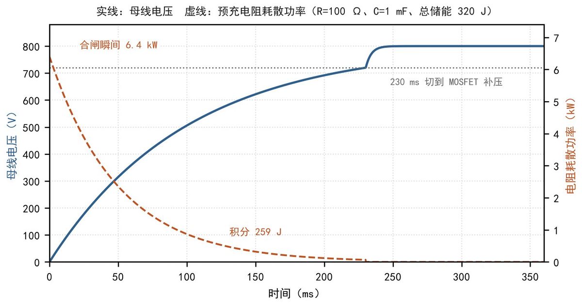
Figure 2: Bus voltage and limiter dissipation during precharge (self-drawn, based on published parameters, not a copy of the original).
Failure scenario: relay fails to close, resistor becomes load
Symptom: after cabinet power-up, input undervoltage is reported, panel shows bus at 62 V, all eight supplies fail to start. Maintenance replaces two modules assuming supply failure, but the issue persists.
Cause: the bypass relay did not close, leaving the 100 Ω precharge resistor in series. A constant-power load with series resistance has no solution; the bus collapses to tens of volts, the resistor sees 6.4 kW, glows red within ten seconds, and burns open within thirty seconds, leaving the bus dead.
Three fixes: after 400 ms, check voltage across the resistor; if it exceeds 5 V, inhibit loading and alarm. Add a 10 A fuse in series with the resistor to open before burnout. Add an auxiliary contact to the relay for status feedback, and include "bypassed" in the cabinet alarm word.
Unique analysis: the hot-swap dividing line is stored energy
The industry treats hot-swap as a component selection problem—"add a limiting element." At 800 V, this framework fails because the real constraint is stored energy, not current. For the same 8 A peak, 48 V corresponds to 1.15 J, while 800 V corresponds to 320 J—exceeding the pulse withstand of any TO-247 device, no matter how fast the limiting loop. The common approach only holds when stored energy is below 10 J, i.e., capacitance below 31 µF at 800 V or 4.3 mF at 48 V. Beyond that, the approach must shift from "select a device" to "split the energy." The number of stages is determined by device withstand divided by total energy: 320 J with 10 J withstand requires at least two stages. The cost of two stages is an extra relay, a power-up sequence, and voltage-difference detection.
Selection: walk through a 30 kW power module
Constraints: 800 V DC input, 30 kW rated, 1 mF input capacitance, power-up time ≤1 s, precharge cost ≤$5 per unit, height ≤10 mm, eight units in parallel in the cabinet.
Three candidates: resistor + relay bypass, single-stage linear 5 A, and staged precharge. Their peak current, charging time, and device energy are in the table above; no new numbers needed.
Single-stage linear is out: 320 J vs. 10 J withstand—no heatsinking can fix that. Pure resistor has only 20% margin; in a 45°C cabinet, resistor surface reaches 180°C, and adjacent electrolytic capacitor life, halving every 10°C rise, drops to 4 years.
Staged precharge is chosen. Three 100 Ω resistors in parallel charge to 720 V in 230 ms; after the relay closes, a 150 V MOSFET performs 16 ms linear topping, then the relay bypasses. Height is 9 mm, cost $4.8, power-up time 246 ms per unit, 2.0 s for eight sequential. The cabinet input busbar is rated 400 A; with sequential power-up, only one unit precharges at a time, so 8 A peaks do not add up, and the busbar need not be upsized.
Costs and risks: sequential power-up makes the eighth unit wait 1.75 s, stretching cabinet ready time from 1 s to 2.0 s. Resistors require 60 s cooling after three consecutive plug-ins; frequent plugging during commissioning may trigger thermal lockout. The MOSFET operates in linear mode for 16 ms; select a 150 V type rated for 5 A linear current per its SOA curve—do not substitute a switching FET.
If input capacitance per unit is below 31 µF, use single-stage linear limiting; the cost is a $1.7 device. If capacitance is around 1 mF and eight units must power up simultaneously, use staged precharge with sequential control; the cost is 2.0 s ready time.
What this means for your build
- Calculate stored energy (½CV²) first. If it exceeds 10 J, a single linear stage will fail—plan for staged precharge.
- Select resistors by pulse withstand, not power rating. Wirewound or aluminum-housed types handle hundreds of joules; chip resistors only a few.
- When using linear limiting, verify the pass device's SOA for the full pulse duration and voltage drop. Do not rely on steady-state current ratings.
- Add detection for relay failure: monitor voltage across the precharge resistor and inhibit loading if it exceeds a threshold.
- For DC systems, use DC-rated contactors or series breaks; AC fuses may not clear arcs and can damage contacts.
One line: The challenge of 800 V hot-swap is distributing 320 J of stored energy, not suppressing 8 A of current. Energy must be split between a resistor stage and a MOSFET stage.
References: Energy Reports, 2021, Vol. 7, pp. 378–387. Title: Soft-starting scheme for a DC solid-state transformer based on a modular multilevel converter. Authors: Zhendong Ji, Rui Rao, Qiantong Wang, Dongye Li, Yichao Sun, Jianhua Wang, Jianfeng Zhao. DOI: 10.1016/j.egyr.2021.08.035. Second source: Sequential Capacitor-Based Closed-Loop Precharge Control during the Single-Phase MMC Start-Up Process, Walid A. M. Ghoneim, Ahmed Alaa Aziz, Energies, Vol. 14, No. 16, Article 4840, 2021, DOI 10.3390/en14164840.
Image notes: Figures 1 and 2 are self-drawn; Figure 1 is a schematic, Figure 2 is redrawn from published parameters, not copies of the original.
Source: compiled from public web sources.