
Link budgets for optical interconnects in data centers routinely set aside 1 dB for reflections and multipath effects. Run the dual-reflection interference math and that allowance looks wildly oversized. An endface that leaves the factory at 45 dB return loss can degrade in the field to 25 dB and still cost an 800G link only about 0.05 dB. To actually consume the full 1 dB, both endfaces would have to fall to 15 dB at the same time — a failure state, not an operating condition.
The short answer: interference amplitude equals twice the square root of the product of the two reflection coefficients, and the penalty is scaled by one third of the PAM4 eye height. A 45 dB endface paired with a 30 dB laser facet yields a signal-to-interference ratio (SIR) of 69 dB and a penalty below 0.01 dB.
Dual-reflection interference depends on just two coefficients
Multipath interference (MPI) is light bouncing between two reflection points in a link and arriving at the receiver coherently with the main signal. It does not need distance — a two-meter patch cord is enough.
The combined relative amplitude is 2 times the square root of the product of the two reflection coefficients. The ratio of signal power to interference power is called SIR and equals 20 times the log of the inverse of that amplitude. Each reflection coefficient comes from return loss: 45 dB corresponds to 3.2 × 10⁻⁵.
The penalty is scaled by the three eyes of PAM4. Eye height is only one third of the swing, so the same amplitude disturbance is effectively tripled, and the power penalty is −10 × log(1 − 3 × amplitude). For small amplitudes this is nearly linear: 2% amplitude maps to 0.27 dB.
A single reflection point does not create interference — it only sends light back. Multipath requires a second reflection point to send it forward again, so the two beams overlap at the receiver. That is why the number of connectors in a link matters more than any single connector's specification. A 16-fiber MPO link strung through four connector pairs has eight reflection points.
When several reflection points coexist, the interference from each pair adds with random phase, and the total amplitude grows with the square root of the number of pairs. Eight points give twenty-eight pairs, 5.3 times the single-pair amplitude, but each pair's coefficients are low, so the aggregate stays under 0.1 dB. This is the reason to control connector count in an MPO link rather than chase return loss on one connector.
45 dB endfaces combine to 69 dB SIR
Short-reach 800G links are still dominated by spans of 500 m or less, and four connector pairs per link is the norm. Plugging in the numbers using published parameters gives a far more optimistic result than intuition suggests. With a 45 dB connector endface and a 30 dB laser facet, the interference amplitude is 0.036%, SIR is 69 dB, and the penalty is 0.005 dB.
Degrade the endface to 25 dB and the amplitude rises to 0.36%, SIR falls to 49 dB, and the penalty reaches 0.05 dB. That condition already counts as dirty in a machine room — dust spots visible to the eye — yet it barely touches an 800G budget.
Compare it with other penalty terms. A 500 m G.652 span at 1310 nm has near-zero dispersion penalty; connector insertion loss of 0.3 dB each across four connectors totals 1.2 dB; transceiver TDECQ margin typically consumes 1 dB. MPI at 0.05 dB does not rank in the top three.
What really eats budget is simultaneous degradation at both ends. At 15 dB on both sides, amplitude is 6.3%, SIR is 24 dB, and the penalty is 0.9 dB — only then does the 1 dB allowance get used. At 12 dB on both sides the penalty is 2 dB and the link is down.
| Endface pair (connector / laser, dB) | Interference amplitude | SIR (dB) | 800G penalty (dB) | Verdict |
| 45 / 30 | 0.036% | 69 | 0.005 | Negligible |
| 35 / 30 | 0.11% | 59 | 0.015 | Negligible |
| 25 / 30 | 0.36% | 49 | 0.047 | Still negligible |
| 15 / 30 | 1.12% | 39 | 0.15 | Replace the patch cord |
| 15 / 15 | 6.32% | 24 | 0.92 | Failure state, budget consumed |
| 12 / 12 | 12.6% | 18 | 2.07 | Link fails |
Table notes: penalties are scaled by one third of the PAM4 eye height at the worst-case constructive phase; SIR is the signal-to-interference power ratio; reflection coefficients are converted from return loss as 10 raised to the negative RL divided by 10.
Phase rotates once per 0.03 K
The table above assumes the worst-case phase. In a real link, the optical path difference between the two reflection points sets the interference phase, and that path difference moves with temperature.
For a two-meter patch cord, fused silica's thermal expansion of 0.55 × 10⁻⁶ per kelvin and refractive index temperature coefficient of 1.2 × 10⁻⁵ per kelvin combine so that the optical path changes about 28 µm per kelvin. At a 1310 nm wavelength, the phase rotates through more than twenty full cycles per kelvin.
That means the MPI penalty measured on the same link at different moments is a random number. Budgeting from a single measurement is betting on phase. Engineering practice can only use the constructive worst case — which also explains why the same module behaves differently in different racks.
Shorter patch cords hold phase more stably. A 0.2 m cord changes optical path by only 2.8 µm per kelvin, roughly two cycles, so phase drift over a rack's service life is limited. A 2 m cord spins through more than twenty cycles, effectively scrambling phase entirely. That is why short patch cords give more predictable MPI behavior.
Phase scrambling is bad for design and good for test. It means some modules in any batch will land on the constructive point, so sampling ten units will hit a worst case at least once. If phase were stable, sampling would miss the problem and it would only surface in the field.
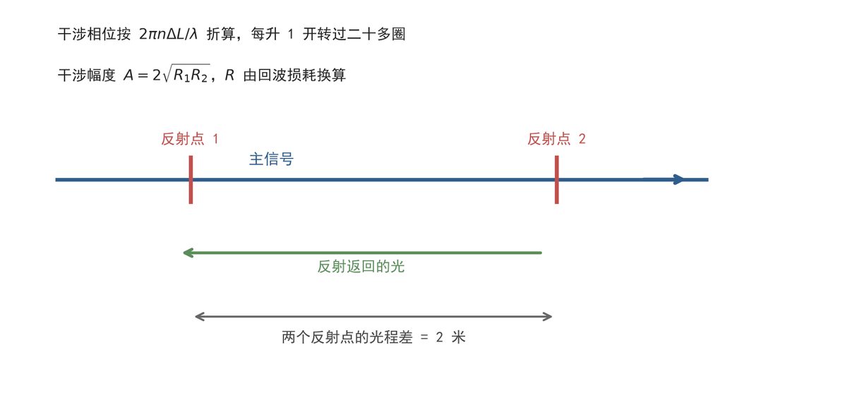
Figure 1 — Optical paths and phase relationship for dual-reflection interference, annotated for a two-meter patch cord at 1310 nm (original schematic, not a reproduction of source artwork).
The 1 dB allowance only holds in a failure state
Setting aside 1 dB for reflections and multipath is a habit carried over from coherent long-haul systems, and it does not hold up for short-reach IM-DD. In long-haul systems the MPI term is comparable to the signal, so 1 dB is not much. Short-reach links have reflection coefficients four to five orders of magnitude lower, making the same allowance conservative by a full order of magnitude. The boundary condition is also hard: only when both endfaces degrade to 15 dB does the penalty approach 0.9 dB; a single endface at 15 dB costs 0.15 dB. The 1 dB does not belong in a normal link budget — it is contingency for a failure state. The claim is falsifiable: if an 800G module measures more than 0.3 dB penalty at a 40 dB endface, the cause is not MPI, and laser feedback or detector reflection should be investigated.
According to published PAM4 evaluations, machine-learning-assisted compensation can push tolerance a further 2 dB near an SIR of 20 dB. That SIR corresponds to roughly 13 dB endfaces at both ends — in the field, a scratched endface. Compensation is a failure-state rescue, not a normal-link budget line.
Effort is better spent on endface cleaning and inspection. Cleaning a 25 dB endface back to 40 dB drops the penalty from 0.05 dB to 0.01 dB, and the recovered budget covers dispersion and jitter. Carrying 1 dB for MPI is buying insurance against an event that does not occur.
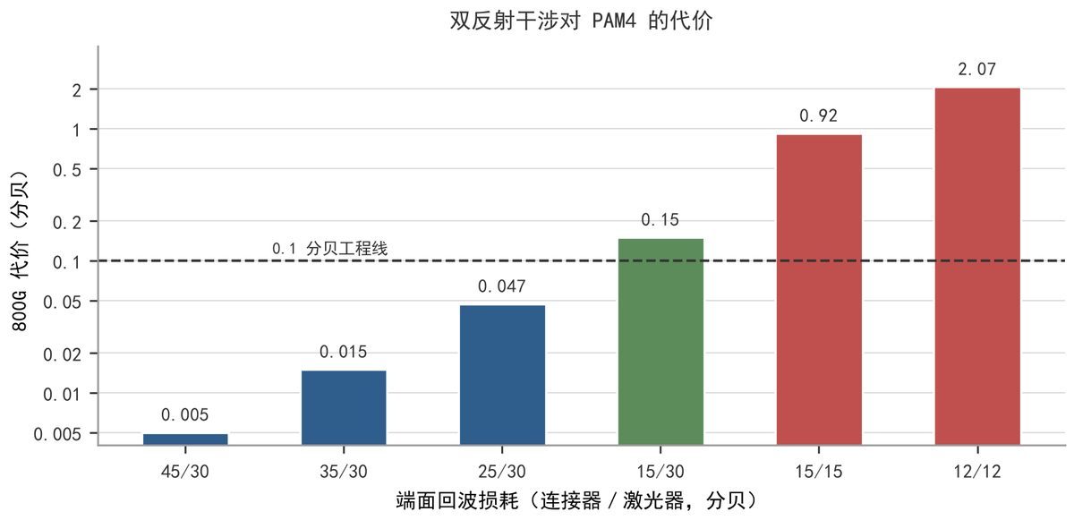
Figure 2 — MPI penalty across endface combinations, with the dashed line at 0.1 dB marking engineering negligibility (original chart redrawn from published parameters, not a reproduction of source artwork).
Failure case: single-wavelength testing hides eight-wavelength spread
An 800G module measured 0.02 dB MPI penalty at 1310 nm on a single wavelength. Installed in an eight-wavelength system, one wavelength rose to 0.4 dB after high-temperature aging.
The cause is that eight wavelengths spaced 4.5 nm apart correspond to interference phase differences of more than a thousand cycles, so each wavelength's phase is uncorrelated. A single-wavelength measurement samples one point; across eight wavelengths, some will always sit near the constructive point.
The remedy is to sweep wavelength during test — measure at least at two wavelengths separated by half a free spectral range and take the larger value. Free spectral range equals wavelength squared divided by group index times optical path difference; for a two-meter patch cord at 1310 nm it is about 0.58 pm, so sweeping wavelength is effectively sweeping temperature.
Working through a selection under constraints
Take these constraints: 800G bidirectional over two fibers, 500 m reach, 3 dB total link penalty budget, of which dispersion and jitter take 0.8 dB and connectors are allowed 0.5 dB, ambient temperature 15 to 40 °C, and two-meter patch cords.
Three candidates. Option A is a standard patch cord at 45 dB from the factory, one MPO at each end. Option B is the same specification plus endface inspection and cleaning procedures guaranteeing 40 dB or better in the field. Option C adds an isolator at the laser to suppress return light by 30 dB.
Item by item: Option A's MPI penalty is 0.005 dB at worst-case phase, apparently the smallest, but field contamination can push it to 0.05 dB with no way to predict it. Option B locks the worst case at 0.015 dB, at the cost of a quarterly endface inspection. Option C suppresses reflections to negligible, at the cost of higher module cost and 0.3 dB extra insertion loss.
Option B wins. The gap between A and B is only the cleaning procedure, while C's extra spend buys an order-of-magnitude reduction on a risk that was already only 0.05 dB — not a good trade.
Verification rests on three things: an endface inspection scope for scratches and dust, a return loss meter, and a bit error rate tester run at both 40 °C and 15 °C. Only when all three pass 40 dB and the penalty difference between temperature points is under 0.05 dB is the MPI item genuinely locked down.
If-then criteria: if MPI already accounts for more than 0.3 dB in the link budget, inspect the endfaces before adding compensation — the cost is a cleaning stop. If endfaces are already above 40 dB and the budget is still tight, then consider an isolator, at the cost of insertion loss and module price.
In one sentence: short-reach links do need a reflection allowance, but 1 dB is copied from long-haul experience — a healthy 800G link is worth about 0.05 dB.
Reference basis: the MPI mechanism and evaluation conventions in this article draw on open-access literature. The table, formulas, case and figures were produced independently.
Primary reference: “Machine Learning-Assisted Mitigation of Optical Multipath Interference in PAM4 IM-DD Transmission Systems,” Photonics, 2025, 12(4):310, DOI 10.3390/photonics12040310 (CC BY 4.0). Secondary reference: “Influence of Optical Feedback Strength on Intensity Noise and Photon Number Probability Distribution of InGaAsP/InP Laser,” Engineering Proceedings, 2025, 87(1):5, DOI 10.3390/engproc2025087005 (CC BY 4.0). Both figures are original schematics or redrawings from published parameters.
What this means for your build
- Do not carry a blanket 1 dB MPI line in a short-reach 800G budget. At 45/30 dB endfaces the real penalty is about 0.005 dB, and even a dirty 25 dB endface costs only 0.05 dB.
- Count connector pairs, not single-connector specs. Eight reflection points in a four-pair MPO link add with random phase and stay under 0.1 dB in aggregate, so reducing connector count beats chasing return loss on one part.
- Budget for endface inspection and cleaning rather than for isolators. Bringing a 25 dB endface back to 40 dB recovers more margin than an isolator that adds insertion loss and cost.
- Test across wavelength and temperature. Phase rotates more than twenty cycles per kelvin on a two-meter cord, so a single-wavelength, single-temperature measurement can miss a 0.4 dB worst case.
- If measured penalty at a 40 dB endface exceeds 0.3 dB, stop blaming MPI and check laser feedback or detector reflection instead.
Source: compiled from public web sources.