
In systems that must stay online while boards are inserted or removed, a hot swap controller manages the inrush current that flows when an unpowered board meets a live backplane. As power demands rise, these controllers must handle ever-higher currents while keeping the pass MOSFETs inside their safe operating area (SOA). This article examines how single-gate and dual-gate hot swap architectures differ in current sharing, using a dedicated demonstration platform to show where each approach succeeds and where it falls short.
Why Paralleling MOSFETs Creates a Sharing Problem
In multi-kilowatt systems, modern hot swap designs commonly place several MOSFETs in parallel to raise output current and lower on-resistance, RDS(ON). This introduces a core difficulty: threshold voltage differences between devices cause uneven current distribution during high-stress transients. The MOSFET with the lowest threshold voltage turns on first and carries most of the current, placing excessive stress on a single device.
It helps to separate steady-state operation from transient operation. In steady state, paralleled MOSFETs generally share current well because the positive temperature coefficient of RDS(ON) naturally balances the devices. During transients, however, the MOSFETs operate in the linear region, where current sharing is highly sensitive to threshold voltage variation and cannot be guaranteed. A single-gate driver paired with paralleled MOSFETs therefore guarantees only the SOA of a single device. To use the full SOA of the paralleled pair, current must be actively shared; otherwise, thermal and electrical stress become unbalanced and can quickly lead to catastrophic failure.
The SOA Limit of Paralleled MOSFETs
The safe operating area defines the voltage, current and duration a MOSFET can withstand safely. When current is unevenly distributed, only the SOA of one MOSFET is assured, which limits the current the system can deliver during state transitions. Faced with this constraint, designers using single-gate controllers must select MOSFETs that can carry the entire load current individually. For high-power hot swap applications with single-gate drivers, this means choosing larger, more costly MOSFETs with higher SOA ratings.
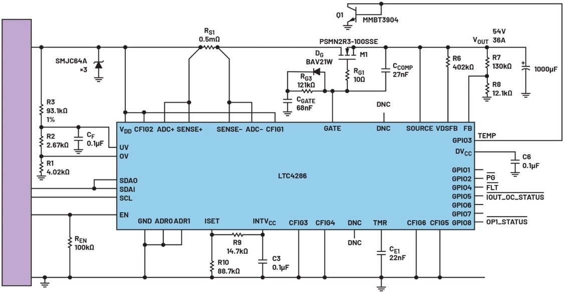
Figure 1: A 54 V, 1900 W hot swap controller.
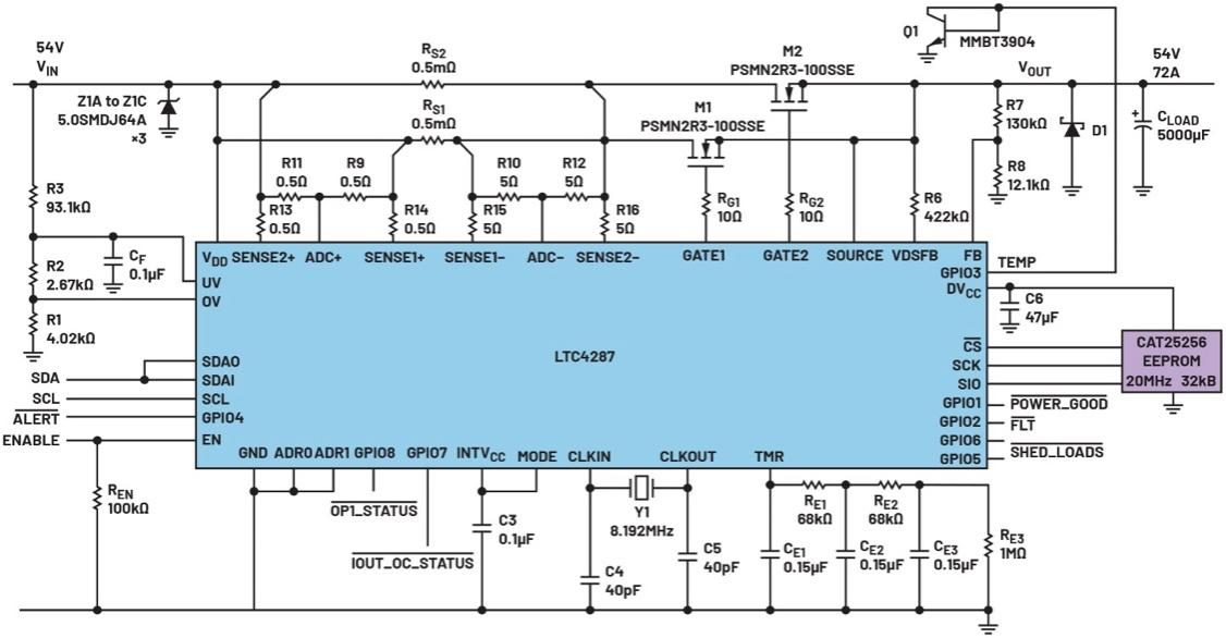
Figure 2: A 54 V, 3900 W hot swap controller in parallel mode.
How the Spirito Effect Further Compresses SOA
When a MOSFET operates in the linear region, thermal instability becomes a key risk. If the device simultaneously sustains high voltage and high current during a transient, the Spirito effect causes uneven current distribution across the silicon die. This creates local hot spots that carry more current and dissipate more power, triggering thermal runaway. This positive feedback mechanism ultimately damages the device and reduces the SOA actually available in practice.
Reliable Current Sharing with a Dual-Gate Controller
A dual-gate hot swap controller uses two independent control loops to drive two gate channels, addressing the limitation described above. This architecture achieves accurate current sharing so that both MOSFET channels can use their full SOA under all conditions. The dual-gate approach effectively doubles SOA capability, supports higher output current and improves overall system reliability. Under high-stress conditions such as startup and fault events, the two MOSFET channels split the load, preventing either device from exceeding its SOA limit.
Figures 1 and 2 show the main architectural differences. A single-gate hot swap controller has only one gate driver (the GATE pin). A dual-gate controller has two gate drivers (GATE1 and GATE2), each with its own current-limit circuit and corresponding current-sense pin.
Evaluating Current Sharing on an SOA Test Platform
To compare single-gate and dual-gate current sharing objectively, a dedicated SOA test platform was developed. The demonstration board accepts both architectures on the same PCB, eliminating device-to-device variation from the comparison. The evaluation used a dual-gate hot swap controller and its corresponding single-gate counterpart. Figures 3 and 4 show the device layout with each controller fitted to the same PCB. The single-gate configuration uses MOSFETs Q1 and Q2; the dual-gate configuration uses Q2 and Q3.
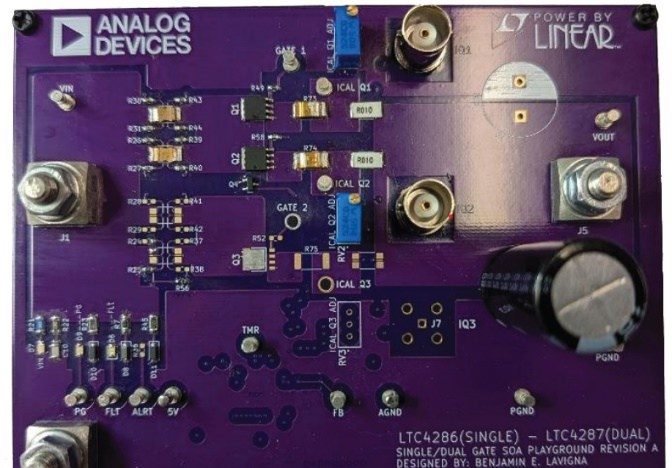
Figure 3: Single-gate demonstration board.
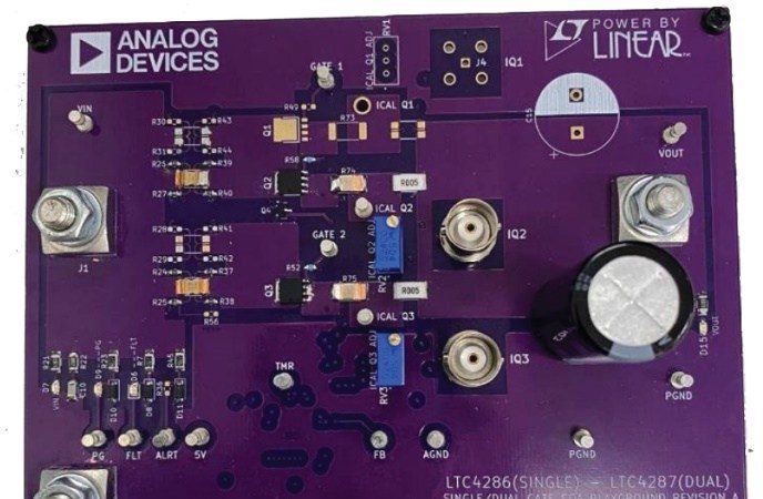
Figure 4: Dual-gate demonstration board.
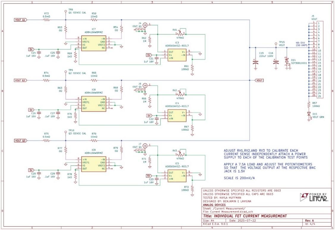
Figure 5: Current-sense arrangement on the SOA test platform.
The current-sense arrangement in Figure 5 measures the current through each MOSFET, enabling an accurate comparison of current sharing between the two approaches.
Selecting MOSFETs to Reproduce Worst-Case Sharing
The test deliberately selected MOSFETs with large threshold voltage differences to reproduce worst-case current sharing. A curve tracer measured the threshold voltage of ten randomly selected N-channel MOSFETs, and the two pairs with the largest threshold spread were chosen for testing.
In the single-gate configuration, Q1 and Q2 measured 2.973 V and 3.147 V respectively. In the dual-gate configuration, Q2 and Q3 measured 2.958 V and 3.121 V. The threshold spreads were 174 mV and 163 mV, keeping the test conditions consistent and demanding so that the comparison between architectures remained fair and unbiased.
Single-Gate vs. Dual-Gate Performance
With the SOA platform built and the MOSFETs paired, current-sharing performance was tested on the bench. Figure 6 shows a standard hot swap test setup with a capacitor bank, the demonstration board and a short-circuit fixture, used for both startup and short-circuit startup tests.
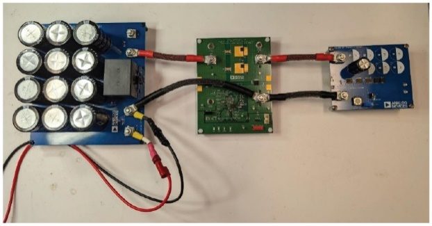
Figure 6: Typical hot swap test setup.
The results below show how each architecture responds under the high-stress conditions of startup and short-circuit startup.
Current Sharing During Startup
Inserting an unpowered board into a live backplane produces a large inrush current. The hot swap controller limits this by managing MOSFET turn-on and slowing the charging rate of the output capacitance. During startup, the MOSFETs operate in the linear region, where current sharing is very sensitive to threshold voltage differences.
The test setup used a 54 V supply and an 81.6 mF capacitor bank feeding the SOA demonstration board. Connecting the capacitor bank triggered startup, and the resulting waveforms were captured for analysis, as shown in Figures 7 and 8.
Tables 1 and 2 compare output current and power dissipation for the single-gate and dual-gate controllers based on the captured waveforms. In the single-gate configuration, the lower-threshold MOSFET Q1 conducted 13.756 A while Q2 conducted only 8.724 A. Q1 dissipated approximately 722 W and Q2 approximately 458 W, a difference of 264 W.
By contrast, the dual-gate controller achieved near-ideal current sharing. Q2 and Q3 each conducted about 10.05 A, and the two devices dissipated essentially the same power (approximately 532 W each).
Table 1: Single-gate output current and power dissipation.
Table 2: Dual-gate output current and power dissipation.
*Total Iin values were measured directly by the oscilloscope.
Figure 7: Single-gate startup waveform at 25°C.
Figure 8: Dual-gate startup waveform at 25°C.
In this 1 kW hot swap application, the power imbalance is already significant. As power delivery requirements continue to grow, this kind of imbalance during paralleled MOSFET operation will be amplified further, increasing SOA stress and degrading current sharing.
Short-Circuit Startup Performance
Short-circuit startup refers to the condition where the output is shorted to ground as the controller turns on. The test used the short-circuit fixture in Figure 6 to accurately simulate a worst-case short event.
The single-gate short-circuit startup waveform in Figure 9 shows severe current imbalance: Q1 conducted 5.11 A while Q2 conducted only 1.25 A, so Q1 saw roughly four times the stress of Q2. In contrast, the dual-gate waveform in Figure 10 shows accurate current sharing, with Q2 conducting 3.14 A and Q3 conducting 3.18 A. This balanced operation distributes stress evenly and lets both MOSFETs share the load safely.
Figure 9: Single-gate short-circuit startup waveform at 25°C.
Figure 10: Dual-gate short-circuit startup waveform at 25°C.
Conclusion
Paralleling MOSFETs in high-power hot swap applications is inherently difficult because of threshold voltage variation. MOSFET datasheets commonly specify a VGS(TH) range of 2 V to 4 V. This wide window introduces substantial uncertainty in current sharing.
As Figure 7 shows, a VGS(TH) difference of only 174 mV can cause the two MOSFETs to differ by about 58% in conducted current and startup power dissipation. In the worst case, with a threshold difference of 2 V, a single MOSFET could carry an even larger share of the current. Designs using single-gate controllers must therefore be conservative and assume that one device carries the entire load current.
It follows that paralleled MOSFETs with a single-gate controller cannot guarantee reliable current sharing. To raise output current with confidence, each MOSFET needs its own gate control, which a dual-gate architecture provides.
Better SOA utilization also brings system-level benefits. Instead of specifying a single large, costly MOSFET to cover worst-case conditions, designers can spread stress across multiple smaller, lower-cost devices while maintaining safe operation.
As power delivery requirements climb into the multi-kilowatt range, accurate current sharing is no longer optional. Dual-gate hot swap controllers provide the control and robustness needed to use the full MOSFET SOA and raise output current.
Choosing the Right Hot Swap Architecture
Traditional single-gate hot swap designs are limited by uneven current distribution and can reliably guarantee only the SOA of a single device. These architectures are therefore typically used in lower-power scenarios, generally below 3 kW, where the overload risk of a single MOSFET is manageable.
Dual-gate hot swap controllers provide independent gate control for each MOSFET, helping to achieve balanced current sharing under a wide range of conditions. This lets both devices use their full SOA, effectively doubling SOA capacity and supporting higher power levels, up to 6 kW.
For applications needing even more power and greater SOA margin, controllers can be paralleled. Using two dual-gate controllers (a four-gate arrangement) further increases current-carrying capability while maintaining accurate current sharing and reliable SOA protection.
What this means for your build
- Plan for threshold spread. When paralleling MOSFETs behind a single gate driver, assume one device may carry the full load current during transients and size the SOA accordingly.
- Use independent gate control for high power. Dual-gate controllers actively balance current during startup and short-circuit events, letting both MOSFETs use their full SOA.
- Verify sharing on the bench. Measure per-device current during startup and short-circuit startup to confirm the sharing you designed for, especially with worst-case threshold pairs.
- Consider the system-level trade-off. Spreading stress across several smaller MOSFETs can be more cost-effective than specifying one oversized device for worst-case conditions.
- Reserve paralleling for the highest power. For requirements beyond what a single dual-gate controller supports, paralleling controllers extends current capability while preserving balanced sharing.
Source: compiled from public web sources.