
Building the series inductance of a dual active bridge into a high-frequency transformer pushes copper loss from 16 W to 33 W. Storing 50 µH of leakage inductance in the same core requires abandoning interleaving, and the AC resistance ratio of an 8-layer conductor climbs from 1.07 to 2.19. Yet the external inductor that gets eliminated would itself dissipate 38 W, so total system loss actually falls by 21 W.
In one sentence: leakage inductance is created by separating primary and secondary windings; giving up interleaving raises the AC resistance ratio to 2.19 and doubles copper loss, but the saved external inductor has higher loss, netting a 21 W system saving.
Leakage inductance is not made with an air gap
Series leakage inductance is the equivalent inductance corresponding to the portion of magnetic flux that does not link between primary and secondary. A dual active bridge (DAB) transfers power through this inductance; for a fixed phase shift, transmitted power is inversely proportional to leakage inductance.
In a line-frequency transformer, inductance is tuned by cutting an air gap—reluctance sits in the gap, easy to calculate and adjust. A high-frequency planar transformer has no air gap; the core is two halves clamped together with only a thin bond line between them. Leakage inductance is determined solely by the winding positions within the window.
Leakage magnetic energy equals half the permeability times the square of field strength, integrated over volume. Field strength is set by the ampere-turn difference between primary and secondary. The closer the two ampere-turn distributions, the smaller the difference and the less energy stored.
So the only way to increase leakage inductance is to move primary and secondary farther apart or to break up the interleaved winding. That path runs directly opposite to reducing copper loss.
Using the DAB power equation—transmitted power equals the product of port voltages times the difference between phase shift and π, divided by twice π squared, frequency, and leakage inductance—with 800 V, 400 V, 20 kHz, and 50 µH, a 27° phase shift delivers exactly 20 kW. If leakage inductance drops to 40 µH, the same power needs only 20°.
Once interleaving is abandoned, layer count drives loss
Interleaving splits 8 conductor layers into several ampere-turn groups of only 2 layers each; the field accumulates only within a group and cancels outside it. The AC resistance ratio then depends only on the number of layers per group, not on total layers.
The approximation is: AC resistance ratio ≈ 1 + (foil thickness ÷ skin depth)^4 × (5 × layers per group² − 1) ÷ 45. Skin depth at 20 kHz and 20°C is 0.467 mm.
With 0.3 mm foil, the foil-to-skin-depth ratio is 0.64, and the fourth power is 0.168. Two layers per group gives 1.07, four layers gives 1.29, and eight layers gives 2.19. Same winding, same copper, but AC resistance differs by a factor of two.
What is easily overlooked is that total layer count does not enter the formula. Sixteen layers fully interleaved, two per group, still gives 1.07; the same 16 layers without interleaving jumps to 5.8. Layers themselves do not create loss—ampere-turn accumulation does. This approximation was published by Dowell in 1966; in sixty years only the coefficients have changed, not the assumptions.
There is another layer. The one-dimensional formula assumes foil width is much greater than foil thickness and ignores field bending at the edges. With 30 mm width and 0.3 mm thickness—an aspect ratio of 100—2D finite element analysis gives an AC resistance ratio about 15% higher than the 1D value. Absolute values should carry a 2.5× margin, but the relative ranking of the five arrangements remains unchanged.
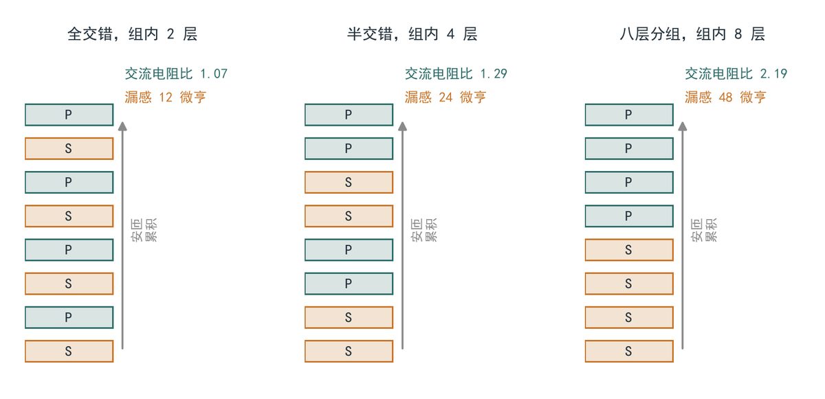
Figure 1: Comparison of three winding arrangements and ampere-turn distributions—left: fully interleaved; middle: semi-interleaved; right: eight-layer grouping (original schematic, not a reproduction of the source figure).
Eight-layer copper loss reaches 33 W
Calculation based on published parameters: 20 kW, 800 V in, 400 V out, 20 kHz, primary RMS current 25 A, winding DC resistance 24 mΩ. DC copper loss equals 25² × 0.024 = 15 W.
Multiplying by the AC resistance ratio gives 16.1 W for interleaved, 19.4 W for semi-interleaved, and 32.9 W for eight-layer grouping. Core loss, estimated at 0.1 T and 20 kHz for nanocrystalline, is 8 W for all three arrangements and does not change with winding.
Core loss deserves separate mention. At 20 kHz and 0.1 T, nanocrystalline specific loss is about 1.6 W/kg; with a 5 kg core, that totals 8 W. This number depends only on core volume and operating flux density—winding arrangement cannot change it.
Copper loss rises from 16.1 W to 32.9 W, an extra 16.8 W. That 16.8 W lands entirely on the transformer, with no increase in heat-dissipating area.
| Winding arrangement (8-layer PCB, 0.3 mm foil) | Layers per group | Leakage inductance (µH, normalized to fully interleaved = 1) | AC resistance ratio | 20 kHz copper loss (W, 25 A RMS) | Verdict (20 kW, 27° phase shift) |
| Fully interleaved, primary/secondary alternating layer by layer | 2 | 12 (0.24) | 1.07 | 16.1 | 38 µH short—external inductor required |
| Semi-interleaved, two-layer groups alternating | 4 | 24 (0.48) | 1.29 | 19.4 | 26 µH short—still external |
| Eight-layer grouping, primary in one group of four | 8 | 48 (0.96) | 2.19 | 32.9 | 2 µH short—acceptable in practice |
| Eight-layer grouping plus magnetic shunting | 8 | 52 (1.04) | 2.19 | 32.9 | Meets target, tolerance ±12% |
| Fully interleaved plus 50 µH external inductor | 2 | 62 (1.24) | 1.07 | 16.1 | Meets target, extra magnetic component |
| Semi-interleaved plus 26 µH external inductor | 4 | 50 (1.00) | 1.29 | 19.4 | Meets target, tolerance ±3% |
Table note: leakage inductance calculated for the same core and window width, normalized to the fully interleaved 12 µH; copper loss includes only the primary-referred value, excluding secondary and terminals; verdict column assumes 20 kW full load and 27° phase shift.
The external inductor loss nobody counts
A 50 µH, 25 A, 20 kHz external inductor has roughly 38 W of copper plus core loss, and occupies 0.3 L plus two terminals. That loss is invisible in a table that compares transformers only.
The 38 W breakdown is worth examining. The winding uses 4 mm² copper tape, 18 turns, DC resistance 9 mΩ, giving 5.6 W copper loss. The core is two EE nanocrystalline halves with a 1.2 mm gap; core loss is 32 W because fringing flux at the gap edges raises local flux density.
Adding the three accounts: fully interleaved plus external inductor = 62.1 W; semi-interleaved plus 26 µH inductor = 47.4 W; eight-layer integrated = 40.9 W. The highest-copper-loss solution has the lowest system loss.
This is the counterintuitive part of the tradeoff. Doubling copper loss does not mean worse efficiency, because loss moves from a separate magnetic component into the transformer, and the move itself saves 21 W—0.1 percentage point at 20 kW.
Volume also needs to be laid out. The external inductor is 0.3 L; with creepage distance for two terminals, it actually occupies 0.35 L. The integrated approach folds this into the transformer, reducing total magnetic volume from 1.25 L to 0.95 L—raising power density from 16 kW/L to 21 kW/L at 20 kW.
There is a small account at the terminals too. The external inductor adds two bolted connections, each 0.3 mΩ, dissipating 0.2 W each at 25 A—0.4 W total. More importantly, these joints loosen under vibration, and contact resistance doubles after two years.
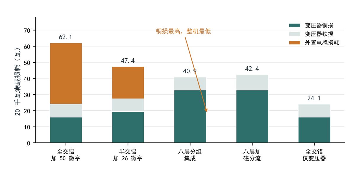
Figure 2: System loss breakdown for five solutions—blue: transformer copper loss; light: core loss; orange: external inductor loss (original chart, redrawn from calculated data in this article).
Capacitance and tolerance are two more accounts
Interleaving brings primary and secondary closer, raising inter-winding capacitance from 96 pF to 380 pF, and common-mode current rises proportionally. The voltage slew rate on the medium-voltage side is unchanged, but the coupling path is nearly four times wider.
At 4 kV/µs and 380 pF, displacement current is about 1.5 A for tens of nanoseconds. This current must return through bearings or Y-capacitors; larger Y-caps in turn slow insulation monitoring.
Leakage inductance is controlled by layer spacing, so a ±10% prepreg thickness tolerance directly becomes ±12% leakage inductance, whereas an external inductor holds ±3%. The threefold difference comes from uncontrolled dielectric thickness; copper foil thickness is actually stable.
A 31 K temperature rise corresponds to a 91°C hot spot, leaving 39 K margin to the 130°C PCB rating. That margin holds only at 60°C ambient and 2 m/s airflow; if the fan stops, thermal resistance rises from 0.75 to 2.1 K/W and temperature rise jumps to 86 K.
When leakage inductance is off by 12%, transmitted power at the same phase shift is also off by 12%, and near 10% load the converter can fall out of soft switching, raising turn-off spikes. The remedy is to test leakage inductance unit by unit at the factory and bin them, then fine-tune with magnetic shunt screws.
Walking through a 20 kW selection
Apply the following constraints: a 20 kW onboard charger, 800 V in, 400 V out, 20 kHz switching, 60°C ambient, 40 K allowable transformer temperature rise, 1.2 L total volume limit.
Three candidates: fully interleaved plus 50 µH external inductor; semi-interleaved plus 26 µH external inductor; eight-layer grouping integrating 50 µH.
Comparison: system loss 62.1, 47.4, 40.9 W; magnetic volume 1.25, 1.18, 0.95 L; terminals 4, 4, 2; transformer temperature rise 18, 21, 31 K.
The eight-layer integrated design is selected. Lowest loss, smallest volume, fewest terminals, and 31 K rise still within 40 K.
Two costs remain. Leakage tolerance relaxes from ±3% to ±12%, requiring an added factory binning step; and leakage inductance is sensitive to lamination thickness, so rework that replaces prepreg changes the operating point and must be re-measured.
What the industry saying leaves out
“Leakage integration saves a magnetic component” only mentions the volume benefit, not where the loss goes. The real boundary is thermal margin, not the efficiency table.
A published prototype reports 99.1% efficiency, measured at the 150 W level where copper loss is under 1 W. Scale the same arrangement to 20 kW: copper loss scales with current squared, core loss only with volume, and hot-spot rise goes from single digits to 31 K.
A falsifiable criterion: if the target leakage inductance is less than twice the natural leakage of a fully interleaved winding, semi-interleaved is sufficient and copper loss rises only 3.3 W. If it exceeds four times, the copper loss increase begins to match the external inductor loss—only then does integration pay, provided at least 15 K of thermal margin remains.
There is also a measurement pitfall. Leakage inductance must be measured at 20 kHz and rated current; an LCR meter at 1 kHz reads about 8% high because winding capacitance begins to shunt at high frequency, pushing the inductance reading up. Binning must use the operating frequency as reference.
In one sentence: integrating leakage inductance buys volume and terminals; the bill is paid in temperature rise, not efficiency.
Reference: independent interpretation of open-access literature. Title: “Optimized coil arrangement for integrating leakage inductance in high-frequency transformers of dual active bridge converters,” by Kianoush Yadollahi and Adel Zakipour, Scientific Reports, 2025, vol. 15, article 35724, DOI 10.1038/s41598-025-19533-2. Secondary source: Energies, 2024, vol. 17, no. 17, article 4258, DOI 10.3390/en17174258. Figure notes: Figure 1 is an original schematic of winding arrangement and ampere-turn distribution; Figure 2 is an original chart redrawn from calculated data in this article, not a reproduction of the source figures.
What this means for your build
- When integrating leakage inductance into a planar transformer, calculate copper loss with the AC resistance ratio for your actual layers-per-group—not total layers. Eight layers in one group gives 2.19× versus 1.07× for interleaved.
- Compare system-level loss, not transformer loss alone. An external inductor can dissipate more than the copper loss you add by integrating, so the integrated solution may win on total loss and volume.
- Check thermal margin before committing. A 31 K rise may fit a 40 K budget at 60°C ambient and 2 m/s airflow, but fan failure can push it to 86 K—verify your worst-case cooling.
- Account for tolerance: leakage inductance from layer spacing can vary ±12% with prepreg thickness, versus ±3% for an external inductor. Plan factory binning and re-measure after any rework that changes lamination.
- Measure leakage inductance at operating frequency and rated current; low-frequency LCR readings can be about 8% high due to winding capacitance.
Source: compiled from public web sources.