
Capacitors sit at the heart of every switching power supply. They store energy, smooth ripple, correct power factor and shunt high-frequency noise away from sensitive nodes. Yet the behavior that makes them useful is often taken for granted. A small bench demonstration with a DC source, a function generator, a couple of capacitors and an oscilloscope makes the underlying physics visible: charge and discharge, DC blocking, AC coupling, and the frequency-dependent impedance that turns a capacitor into a noise sink at high frequency and an open circuit at low frequency.
For hardware teams, the payoff is practical. Understanding these three behaviors helps you choose capacitance values, equivalent series resistance (ESR) and dielectric materials that keep a converter stable across load and temperature. It also explains why a 100 nF ceramic and a 100 µF electrolytic are not interchangeable, and why placement and return path matter as much as the value printed on the case.
What a capacitor actually does
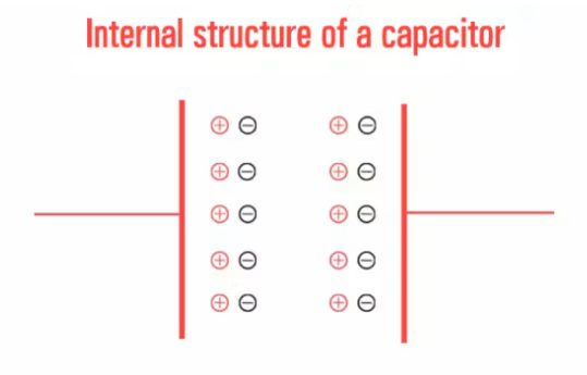
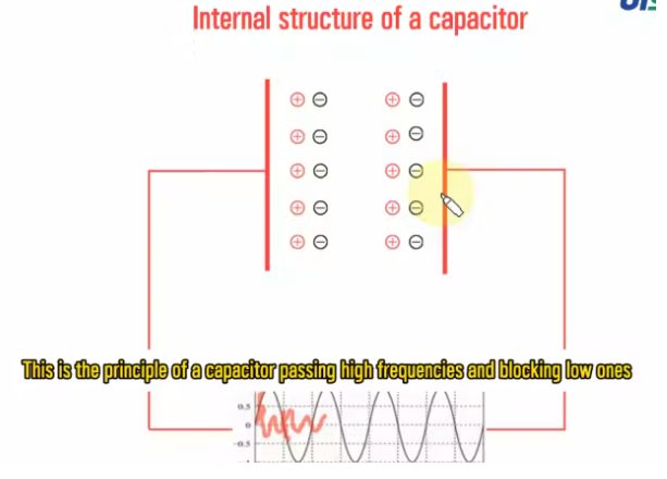
A capacitor is two conductive plates separated by an insulating dielectric. Connect it to a DC source and electrons accumulate on the negative plate while being pushed off the positive plate. No charge crosses the dielectric. As charge builds, the electric field strengthens until the voltage across the plates equals the applied voltage. At that point net electron movement stops and the capacitor looks like an open circuit to DC.
The demo hardware is deliberately simple: an adjustable 0–12 V DC lab supply or a 5 V USB breakout, a low-frequency signal generator covering roughly 1 Hz to 100 Hz, a 1 µF film or ceramic capacitor rated for the applied voltage, a 100 µF electrolytic, a small 3 V/5 V filament lamp or a 5 mm LED with a 220 Ω series resistor, a double-pole double-throw switch for manually reversing polarity, a two-channel digital storage oscilloscope or multimeter, and a breadboard with clip leads.
Charging, discharging and the lamp test
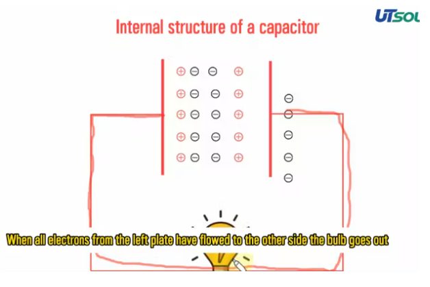
Put a lamp or LED in series with a pre-charged capacitor and the charge and discharge cycle becomes visible. During charging, current flows briefly, the lamp flashes and then goes dark as the plates reach full charge. Remove the supply and short the capacitor across the lamp: the stored electrons flow back to neutralize the positive plate, the lamp lights briefly, and the capacitor discharges to zero.
This is the same energy storage that lets an input electrolytic ride through MOSFET switching transients and hold up the rail between line cycles. The visible flash is a reminder that the capacitor is a temporary energy reservoir, not a resistor.
Blocking DC while passing AC
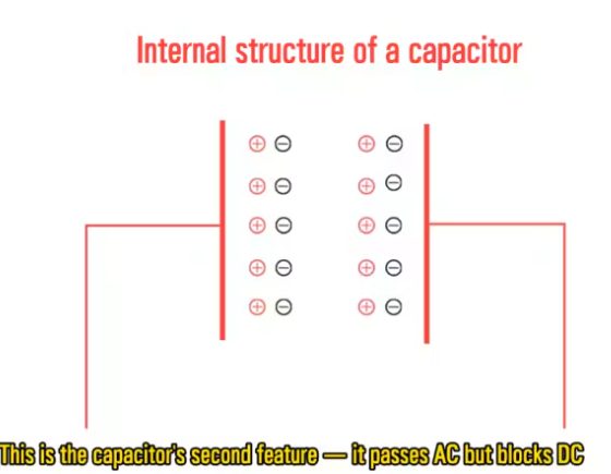
A capacitor physically blocks steady DC current, but repeatedly reversing the supply polarity forces the plates to charge, discharge and recharge in the opposite direction. Current flows in the external wires on every polarity change even though no single electron crosses the dielectric barrier. In circuit terms, AC passes through the loop while DC does not.
That property is used deliberately in isolated flyback and half-bridge gate-drive transformers, where a DC-blocking capacitor prevents DC core saturation while passing the high-frequency drive signal. It is also the basis of AC coupling in signal chains.
Frequency response: why low frequencies are blocked
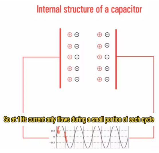
Capacitive reactance is inversely proportional to frequency, Xc = 1 / (2πfC). At 1 Hz with a 1 µF capacitor, each half cycle lasts 500 ms, far longer than the RC charging time constant of a typical circuit. The capacitor saturates early in the half cycle and current stops for the remainder. The result is a high impedance and heavily restricted current flow.
This is the low-frequency end of the filtering story: the capacitor is essentially an open circuit and does little to pass the signal.
Frequency response: why high frequencies pass
Raise the input to 100 Hz or higher and the switching period becomes much shorter than the time needed to saturate the plates. The AC voltage reverses polarity before the capacitor can fully charge and block current, so current flows freely every cycle and reactance Xc falls to a very low value. High-frequency switching noise is easily bypassed to ground or passed on to the next smoothing stage.
This is the mechanism behind output ceramic filter capacitors in the 100 nF to 10 µF range. At switching frequencies from 100 kHz to 2 MHz their reactance is low enough to short PWM noise directly to ground. Input electrolytics play a different role: they buffer 50/60 Hz line ripple, block DC feedback and supply instantaneous energy during MOSFET switching transients.
From bench demo to power supply layout
The same principles translate directly into design choices. A capacitor that looks ideal on a schematic becomes a resonant element once package inductance and PCB trace inductance are included. Effective decoupling therefore depends on a short, low-inductance path from the capacitor to the power pin and a solid return plane underneath.
Dielectric choice matters too. Ceramic capacitors with high dielectric constants lose capacitance under DC bias and temperature, while electrolytics have higher ESR that affects ripple and loop stability. Mixing a bulk electrolytic with a small ceramic is common because each covers a different frequency band.
What this means for your build
- Place high-frequency decoupling capacitors as close as possible to the switching device and its power pins, with a direct return path to ground.
- Use a bulk electrolytic for low-frequency ripple and hold-up, and ceramic capacitors for high-frequency bypass; do not expect one part to cover both bands.
- Account for DC bias and temperature derating when selecting ceramic dielectrics, especially in compact high-density layouts.
- Keep the AC current loop between the capacitor and the switching device small to reduce radiated noise and parasitic inductance.
- Verify filtering on the bench with an oscilloscope before release, since layout parasitics can shift the effective impedance well away from the datasheet curve.
Source: compiled from public web sources.